

Request a free quote Phone Icon
die cutting materials

Blog

7 Best Valve Positioners for Industrial Applications

In process plants, a valve does not regulate flow accurately by itself. A Valve Positioner translates a control signal into precise actuator movement, helping the valve reach its intended position. Small errors matter. A drifting actuator can affect pressure, temperature, product quality, or energy use. Yet selecting equipment is rarely as simple as choosing the most feature-rich model. No shortlist is perfect.

Grand View Research estimated the global industrial automation market at $205.86 billion in 2022 and projected a 9.3% compound annual growth rate through 2030. This wider market forecast reflects growing investment in automated operations, not direct sales of valve positioners. The distinction matters. Plant engineers still need to match each device to its process conditions, actuator type, control signal, and maintenance capabilities.

This guide examines seven valve positioners for industrial applications, comparing practical features such as pneumatic or digital operation, diagnostics, accuracy, and ease of commissioning. Buyers should also check material compatibility, hazardous-area requirements, and support from the manufacturer. A polished specification sheet cannot replace a careful application review. The right choice depends on the valve, the process, and the people who must keep it working.
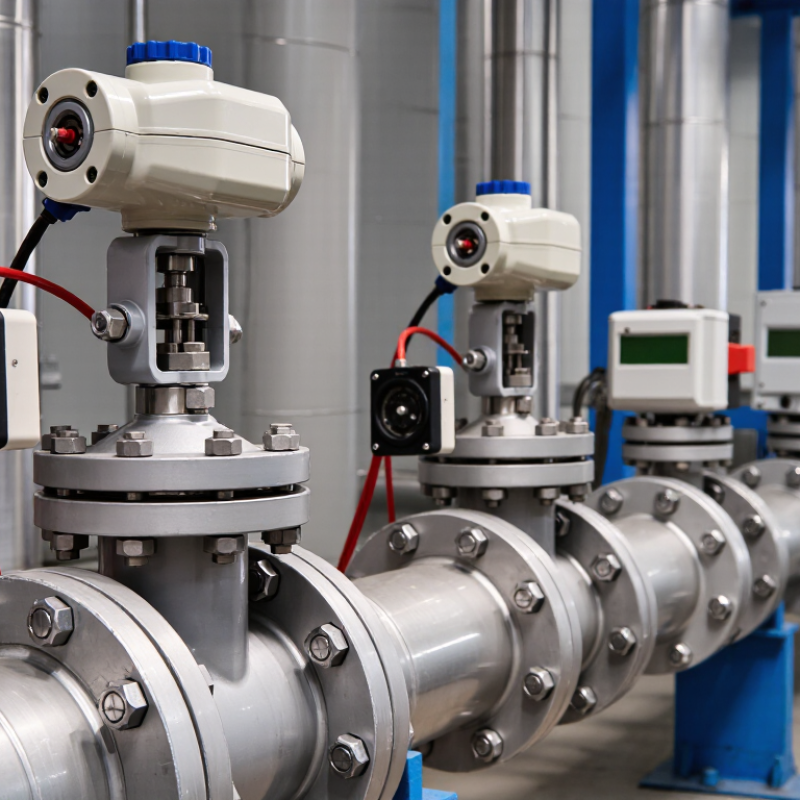
7 Best Valve Positioners for Industrial Applications

What Valve Positioners Do in Industrial Control Systems

A valve positioner helps a control valve follow the command sent by an automation system. In a typical loop, a controller measures a process value, such as tank level or pipeline pressure, then requests a valve opening. The positioner compares that request with feedback from the valve stem or shaft. If the valve is short of its target, the positioner adjusts air pressure to the actuator. The movement is checked again.

Small changes matter.

This feedback can improve response when process pressure, friction, or actuator load changes. For example, a valve regulating steam may need frequent, fine adjustments as demand shifts. Positioners can also support calibration and provide status information, depending on the device and control system. They do not fix every valve problem. A sticking stem, leaking air line, or poorly sized actuator can still cause unstable control.

That assumption is not always safe. Maintenance teams should check the valve, actuator, air supply, and positioner together rather than treating one reading as proof of correct operation.

Selection also depends on signal type, operating conditions, required accuracy, and the plant’s maintenance capabilities. A precise device is useful only when installed and configured correctly.

How Mechanical, Pneumatic, and Digital Positioners Work

A valve positioner compares the control signal with the valve stem’s actual travel, then adjusts actuator pressure to reduce the error. Mechanical positioners use levers, cams, and springs; they are straightforward but can wear or drift. Pneumatic models convert a pressure signal into actuator movement and suit plants with pneumatic control systems. Digital positioners use sensors and electronic control to track travel, tune response, and report faults. They offer more diagnostic detail, but require compatible wiring, configuration, and maintenance skills.

The choice affects more than accuracy. A slow valve may cause temperature or pressure to swing; an overly aggressive setting can make it hunt, visibly shaking the linkage. McKinsey Global Institute’s 2015 report, The Internet of Things: Mapping the Value Beyond the Hype, estimated predictive maintenance could reduce maintenance costs by 10–40% and equipment downtime by up to 50%. Those are broad industrial estimates, not guaranteed savings from a positioner. Digital diagnostics can support condition-based maintenance, but only when teams review the data and verify faults in the field.

Tips: Match the positioner to actuator type, supply pressure, hazardous-area requirements, and desired diagnostics. Before tuning, check for sticky packing, loose linkages, and air leaks; software cannot fix bad mechanics. Record baseline travel and response time. Small details matter. A clean trend can still hide a poorly calibrated valve.

7 Best Valve Positioners for Industrial Applications — How Mechanical, Pneumatic, and Digital Positioners Work
Positioner Type Typical Control Input How It Works Key Advantages Considerations Best-Fit Applications
1. Mechanical-Pneumatic Positioner Pneumatic control signal, commonly 3–15 psi (approximately 0.2–1.0 bar) A mechanical linkage senses valve-stem or shaft movement. A force-balance mechanism and pneumatic relay adjust actuator pressure to reduce the difference between commanded and actual position. Simple operating principle; can provide more actuator force and improve response compared with operating an actuator directly from the control signal. Linkages require correct alignment and may need periodic inspection. It requires a clean, dry instrument-air supply and does not provide built-in digital diagnostics. Legacy pneumatic control systems and installations where electronic signals are unavailable or unsuitable.
2. Pneumatic Positioner Pneumatic pressure signal, often 3–15 psi (approximately 0.2–1.0 bar) The positioner compares input pressure with mechanical position feedback, then meters instrument air to or from the actuator until the valve reaches the commanded position. Works without an electrical control signal at the valve; suited to pneumatic control infrastructure and certain classified-area installations. Needs a reliable instrument-air supply. Air quality, tubing condition, and calibration affect performance; remote electronic monitoring generally requires additional equipment. Plants with pneumatic controllers, air-operated actuators, or process areas where local electrical devices are restricted.
3. Analog Electro-Pneumatic Positioner Usually a 4–20 mA analog signal An electro-pneumatic transducer converts the electrical command into a pneumatic force or pressure. The positioner uses valve-travel feedback and a pneumatic relay to regulate actuator pressure. Connects an electronic control system to a pneumatic actuator; widely compatible with conventional analog control loops. Typically provides limited diagnostic information compared with digital models. It still depends on instrument air, and electrical compatibility must be checked. General-purpose control valves in plants using standard 4–20 mA control signals.
4. Digital Smart Positioner Commonly 4–20 mA; some models also support digital communication A microprocessor reads the command and position feedback, then controls pneumatic output. Depending on the model, it can support automatic setup, status reporting, and diagnostic functions. Can simplify commissioning and provide useful information about travel, response, and device condition. Features vary by model and protocol. Configuration may require compatible tools, and the device still needs suitable air supply and actuator sizing. Control valves where easier setup, maintenance insight, or improved monitoring is valuable.
5. HART-Enabled Positioner 4–20 mA analog signal with HART digital communication superimposed on the loop The analog current provides the control command while a compatible host can exchange additional digital configuration and diagnostic data over the same wiring. Can add remote configuration and device information without replacing an existing 4–20 mA control architecture. Requires compatible host equipment and correct loop design. HART capability and available diagnostic functions differ among devices. Facilities that want smart-device access while retaining conventional analog control loops.
6. Fieldbus Positioner Digital fieldbus communication, such as FOUNDATION Fieldbus or PROFIBUS PA, depending on the device The controller sends commands and receives device data through a digital network rather than relying solely on a dedicated analog current command. Supports digital communication and device data on the network; may reduce point-to-point signal wiring in appropriately designed systems. Must match the plant’s protocol, network design, power arrangement, and engineering tools. Not every fieldbus device or installation uses the same wiring or power scheme. Plants designed around a compatible digital fieldbus architecture and centralized device management.
7. Double-Acting Pneumatic Positioner Typically a pneumatic signal or an electrical command converted to pneumatic control For a double-acting actuator, the positioner directs air to one actuator chamber while venting or controlling the other, and reverses the action as needed using position feedback. Controls actuators that use air pressure for movement in both directions; can support precise positioning of compatible rotary or linear valves. Requires two appropriately connected actuator ports and a suitable air supply. Fail action depends on the actuator and system design; it should not be assumed to fail open or closed. Double-acting pneumatic actuators on rotary or linear valves where powered movement in both directions is required.
Selection note: Positioner categories can overlap—for example, a digital positioner may also use HART communication. Confirm input signal, communication protocol, actuator type, required fail action, hazardous-area approvals, air quality, and operating conditions against the specific valve and plant requirements.

Key Criteria for Selecting an Industrial Valve Positioner

Selecting an industrial valve positioner begins with the valve and actuator, not a feature list. Check actuator type, required travel, and available air supply. A unit must move the valve reliably across its operating range, including when process pressure changes. Small details matter. Confirm that the input signal and feedback method match the control system before comparing models.

Accuracy and response time should suit the process. A fast response can help where flow changes quickly, but excessive sensitivity may cause unnecessary movement or wear. Consider the fluid, temperature, vibration, and moisture around the installation. Dusty areas or washdown zones may require stronger enclosure protection. If the positioner will be fitted to an existing valve, verify mounting dimensions and linkage compatibility; assumptions here can add hours to commissioning.

Maintenance needs deserve equal attention. Clear calibration steps, accessible diagnostics, and replaceable parts can reduce troubleshooting time. Ask how the device reports faults and whether technicians can check position locally. Test it under load. Bench settings do not always reflect real operating conditions. A practical selection balances control performance with the skills, tools, and service access available at the site. Some requirements may remain uncertain until the equipment is installed, so document those assumptions and review them during commissioning.

Seven Leading Valve Positioners and Their Distinctive Features

Valve positioners serve the same basic purpose: matching valve travel to a control signal. Their distinctive features suit different plant conditions. A pneumatic positioner uses an air signal and has a simple operating principle, which can be useful where electronic controls are limited. An electro-pneumatic model converts an electrical command into pneumatic movement, fitting common control systems. Digital positioners add configurable settings and precise feedback. Smart diagnostic models can flag issues such as rising friction or slow response before they become obvious during operation. Useful, but not magic.

The remaining choices address installation and actuator needs. A linear-stem positioner is designed for valves that move in a straight line, while a rotary positioner matches quarter-turn valves. A remote-mount positioner keeps sensitive electronics away from heat, vibration, or difficult access points. That separation may simplify maintenance, though it adds installation considerations. Selection should account for actuator type, signal compatibility, air supply, environment, and required feedback. Check the full operating range, not just the normal setpoint. A datasheet can narrow the options, but it cannot capture every site condition. I would still verify response and mounting details against the actual valve assembly.

Matching Valve Positioners to Industrial Applications

Matching a valve positioner to an application starts with the valve, actuator, and process conditions—not a popularity list. Pneumatic positioners suit plants with dependable instrument-air systems and straightforward control needs. Electro-pneumatic units accept electrical signals while operating pneumatic actuators, making them practical where controllers are electronic but valves remain air-powered. Digital positioners add diagnostics and configurable response, useful when maintenance teams need travel data or alerts.

More features are not always better.

Consider the operating environment. A positioner near a vibrating pump, exposed to washdowns, or installed outdoors needs suitable enclosure protection and stable feedback. For a throttling valve that cycles often, response time and repeatability matter; for a rarely adjusted isolation valve, elaborate diagnostics may bring little value. Check actuator sizing, air quality, signal compatibility, hazardous-area requirements, and available maintenance skills before selecting a model. Fit matters most. A technically capable unit can still perform poorly if tubing is restrictive, calibration is rushed, or linkage alignment is off by a few millimeters.

That detail gets missed.

Commissioning should include stroke checks, leak inspection, and a comparison between commanded and actual travel under realistic process conditions. No selection chart captures every installation, so leave room to verify assumptions on site.