Why Choose Aluminum Spacers for Industrial Projects?
An Aluminum Spacer may look minor beside a press frame, conveyor, or machine enclosure. Yet it sets clearance, supports alignment, and can help prevent metal surfaces from rubbing. In industrial projects, these small components face vibration, moisture, temperature changes, and repeated maintenance. Their material choice affects more than weight. It can influence installation time, service life, and replacement needs.
Aluminum is often considered because it offers useful strength at relatively low weight and forms a protective oxide layer. The International Aluminium Institute’s Aluminium Sector Greenhouse Gas Pathways to 2050 report estimates that the sector contributes about 2% of global human-made greenhouse gas emissions. That figure describes the wider aluminum industry, not the footprint of any individual spacer. Still, it highlights why engineers should consider material quantity, production, and service life together. A lightweight part is not automatically a lower-impact part.
Fit matters, too. Engineers should check the alloy, dimensions, load, temperature range, and exposure conditions before specifying an Aluminum Spacer. For example, a spacer beside a washdown area may need different corrosion protection from one inside a dry, enclosed assembly. The exact alloy and finish matter. So does tolerance. An undersized or poorly machined spacer can introduce movement rather than prevent it. Aluminum can be a practical choice, but it is not universal. Real operating conditions should decide.
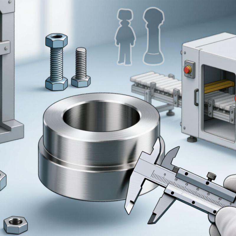
Aluminum Spacer Fundamentals: Typical Density Is 2.70 g/cm³
Aluminum spacers are often chosen when a project needs separation without adding much mass. A typical density for aluminum is about 2.70 g/cm³, though the exact value varies slightly by alloy. This figure helps estimate weight before parts are made. For example, a plain spacer measuring 100 × 50 × 10 mm has a volume of 50 cm³. At 2.70 g/cm³, its estimated mass is 135 g. A useful baseline.
Real parts may weigh less if they include holes, slots, or cut corners. Density is only one design factor, not a measure of strength or service life. Alloy, thickness, temperature, and loading conditions also matter. An aluminum spacer in a lightly loaded fixture may work well, while the same dimensions could be unsuitable under heavy clamping. That judgment needs actual specifications. In practice, I would confirm the alloy and dimensions with the supplier, then compare the estimate with a finished part. The calculation is simple, but small details can shift the result. Small details matter.
How Spacers Control Gaps, Alignment, and Load Transfer
Why Choose Aluminum Spacers for Industrial Projects?
How Spacers Control Gaps, Alignment, and Load Transfer
Aluminum spacers create a fixed gap between machine parts, plates, or mounting surfaces. That small distance can keep a rotating component clear of its housing or align two bolted parts. When the spacer’s thickness matches the design, fasteners can clamp the assembly without pulling surfaces out of position. In practice, a clean, even face matters. Burrs or uneven contact can quietly spoil alignment.
Spacers also help carry compression through an assembly. A properly sized spacer transfers clamp force between mating parts, rather than leaving an unsupported gap. Aluminum is lightweight and easy to machine, which can help when parts need custom lengths or precise bores. But it is not automatically right for every load. Thin sections may deform under excessive pressure, and repeated checks may reveal small shifts that a drawing did not predict. That is worth considering.
Tips: Measure the gap at several points. Check spacer faces for burrs, then verify alignment after tightening. Confirm the load and temperature before selecting thickness and alloy.
Why Choose Aluminum Spacers for Industrial Projects? - How Spacers Control Gaps, Alignment, and Load Transfer
| Spacer configuration | Representative dimensions | Gap and alignment control | Load-transfer behavior | Common industrial use |
| Machined solid spacer | Typical thickness: 1–50 mm; custom shapes and hole patterns | A controlled thickness sets a fixed gap; parallel faces help maintain component alignment. | Transfers compression through its contact faces. Check contact area, flatness, and local bearing stress. | Machine frames, equipment mounts, brackets, and structural assemblies. |
| Shim or shim stack | Individual sheets are commonly about 0.05–1 mm thick; stack thickness is adjustable. | Fine gap correction by adding or removing layers; useful for leveling and alignment adjustment. | Carries compressive load when fully supported and clamped; thin or unsupported edges can deform. | Motor and pump alignment, machine leveling, and assembly tolerance correction. |
| Tubular spacer sleeve | Length and inside diameter are selected to suit the bolt and assembly; often made to drawing. | Maintains separation between plates or components and provides a defined bolt-clearance path. | Transfers clamping force through the sleeve ends. End squareness and wall thickness affect load distribution. | Bolted joints, guards, enclosures, and assemblies requiring controlled stand-off. |
| Precision stand-off | Specified by stand-off length, bore, outside diameter, and end-face requirements. | Maintains a repeatable distance between mounted parts; concentric bores can help locate fasteners. | Transfers compression along its axis; avoid using a slender stand-off as a bending support unless designed for it. | Instrument panels, electrical enclosures, sensor mounts, and modular equipment. |
Material and design reference - Aluminum alloy 6061-T6 has a typical density of about 2.70 g/cm³ and an elastic modulus of about 69 GPa. Actual strength depends on product form, dimensions, and applicable material specification.
- A first-pass bearing-stress check is compressive force divided by effective contact area. Verify the spacer, mating parts, fasteners, and joint against the project’s design loads and safety requirements.
- Representative dimensions are selection guidance, not guaranteed manufacturing tolerances or load ratings. Confirm the alloy, temper, finish, dimensions, tolerances, and operating environment in the part specification.
Weight Comparison: Aluminum at 2.70 vs. Steel at 7.85 g/cm³
For an industrial spacer with the same dimensions, density makes a clear difference. Aluminum is about 2.70 g/cm³, while steel is about 7.85 g/cm³. That makes aluminum roughly 65.6% lighter by volume. A 100 cm³ spacer would weigh about 270 grams in aluminum and 785 grams in steel. The difference is 515 grams per part. Across 500 spacers, that is about 257.5 kilograms less material to handle and move.
That reduction can matter on a machine frame, an adjustable fixture, or a large assembly with many stand-offs. Lighter components may be easier to position overhead and can reduce moving mass in equipment. Small detail. Still, density is not strength. Alloy, wall thickness, spacer length, and loading all affect performance. A lightweight part that bends or crushes is no advantage.
Material choice needs a closer look. Check the required load, deflection limits, vibration, operating temperature, and contact with nearby metals. Aluminum expands more with heat than steel, which may affect tight tolerances in a warm assembly. Density values are useful for estimates, not a complete design check. It is easy to focus on the weight saving and overlook the interface; that deserves a second look.
Alloy Selection: 6061-T6 Has a Typical Tensile Strength of 310 MPa
For industrial spacers, 6061-T6 offers a useful balance of strength, weight, and machinability. Its typical ultimate tensile strength is about 310 MPa, or 45 ksi, according to commonly published 6061-T6 property data, including ASM Handbook, Volume 2. That figure describes resistance to pulling before failure. It is not the allowable design stress. Keep that distinction clear.
The Aluminum Association’s Aluminum Standards and Data and ASTM specifications show why alloy figures need context: required properties depend on product form and dimensions. A spacer machined from plate may not match one made from extruded bar. Check the material certificate, temper, and applicable product specification before relying on 310 MPa. Small detail, big consequence. In service, a spacer may face clamp loads, vibration, and uneven contact around a bolt hole. Tensile strength alone cannot predict those conditions. Verify compressive loading, fit, and fatigue requirements for the assembly. And be honest: a strong alloy will not rescue poor tolerances or an unsupported design.
Why Choose Aluminum Spacers for Industrial Projects?
Typical ultimate tensile strength by aluminum alloy and temper
6061-T6 offers a typical ultimate tensile strength of 310 MPa, providing a useful balance of strength, machinability, and corrosion resistance for many industrial spacer applications. Values are typical reference figures and can vary with product form and specification.
Design Checks: Aluminum’s Thermal Expansion Is About 23 µm/m·°C
Aluminum spacers are light, corrosion-resistant, and easy to machine, but their dimensions change with temperature. European Aluminium’s materials data gives a typical expansion coefficient near 23 µm/m·°C; ASM Handbook data for common aluminum alloys reports values around this range. For a one-meter spacer stack exposed to an 80°C temperature rise, the estimated growth is about 1.84 mm. That is not trivial. A few millimeters can shift a machine guard, alter a bearing gap, or load a bolted joint.
Use the calculation ΔL = α × L × ΔT as an early design check, not a final guarantee. Alloy, temperature range, and component geometry affect actual movement. Check the hottest operating condition against the mating steel parts, whose expansion is lower, and consider whether the assembly can slide or needs a fixed datum. For example, a slotted mounting hole may accommodate movement, while a tightly clamped spacer may transfer stress elsewhere. ASM Handbook material-property tables are useful for selecting alloy-specific values; confirm them against supplier test data when tolerances are tight. I would also question a design that assumes the whole assembly warms evenly. Real equipment rarely does. A motor-side spacer may heat faster than the frame, and that unevenness can matter more than the nominal coefficient.