


Request a free quote Phone Icon
die cutting materials

Blog

How to Choose Low Voltage Switchgear in 2026?

Choosing Low Voltage Switchgear in 2026 requires more than comparing prices, ratings, and cabinet finishes. The right selection protects people, equipment, and production continuity. It must also match the installation’s voltage, fault level, load profile, environment, and future expansion plans. A food-processing plant may need stainless steel enclosures and washdown protection. A data center may prioritize selective coordination and heat management. Small details matter.

This guide examines practical selection criteria, including rated current, short-circuit withstand strength, ingress protection, busbar design, thermal performance, monitoring, and maintenance access. It also considers IEC 61439 verification, IEC 60947 component requirements, and applicable local electrical regulations. Standards help, but they do not replace engineering judgment. That assumption fails.

Experienced engineers often review single-line diagrams, cable sizes, ambient temperatures, and available fault current before approving equipment. They also check the manufacturer’s test documentation, quality controls, service support, and spare-parts availability. A low purchase price can become expensive when ventilation is poor or replacement parts are unavailable. Field conditions are rarely as clean as the original specification.

Some recommendations may need adjustment. Building layouts change. Loads grow. Standards are updated. Therefore, every decision should be verified by a qualified electrical professional and coordinated with the project’s authority requirements. The goal is not to select the biggest enclosure or the cheapest panel. It is to choose dependable Low Voltage Switchgear that performs safely, remains serviceable, and supports the facility’s real operating demands.
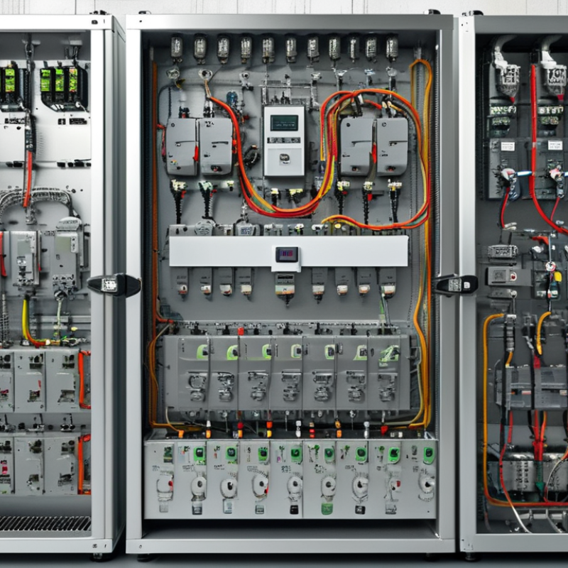
How to Choose Low Voltage Switchgear in 2026?

Define Low-Voltage Scope: ≤1,000 V AC or ≤1,500 V DC

In 2026, define low-voltage scope before comparing switchgear designs. IEC 61439-1 covers assemblies rated up to 1,000 V AC or 1,500 V DC. This boundary matters because insulation coordination, testing, clearances, and protection requirements change beyond it. A 690 V AC motor panel and a 1,500 V DC solar combiner may both be low-voltage, yet they face very different fault behavior and switching stresses.

Start with the actual system voltage, not the label on the equipment schedule. Record maximum operating voltage, frequency, prospective short-circuit current, load type, and earthing arrangement. IEC 60947-2 supports this protection-focused evaluation. For DC systems, confirm polarity, interruption capability, and stored-energy discharge time. DC arcs can persist. That detail is easy to underestimate.

The IEA Electricity 2024 report forecasts global electricity demand growth averaging 3.4% annually from 2024 through 2026. More demand can mean denser panels, larger feeders, and higher fault levels. Select assemblies against the calculated worst case, then verify temperature rise, IP rating, altitude correction, and internal separation under IEC 61439 testing principles.

Independent design review is valuable here. My practical concern is simple: engineers sometimes choose a familiar 400 V arrangement for a 1,000 V application, assuming similar behavior. It is not similar enough.

Document every assumption, especially when future expansion remains uncertain.

Match IEC 61439 Assembly Design to Load, Fault Level, and Environment

How to Choose Low Voltage Switchgear in 2026?

Low voltage switchgear should match the real duty, not only the drawing. IEC 61439 assembly design starts with rated current, diversity, and future expansion. Record normal loads, motor starting currents, and possible overloads. Then check the prospective short-circuit current at the installation point. The assembly’s short-time withstand rating must exceed that value. A neat enclosure can still be the wrong choice.

Environment changes the design. A dusty workshop may need stronger ingress protection and careful ventilation. Outdoor equipment requires attention to rain, sunlight, condensation, and corrosion. Temperature rise also matters inside a crowded cabinet. Leave practical space for cable bending and maintenance access. I have seen projects where fault calculations were correct, but heat and access were underestimated.

Tips: Request the IEC 61439 verification documents. Confirm temperature-rise, short-circuit, and dielectric test evidence. Check the assembly rating at its actual installation temperature. Ask an electrical engineer to review discrimination between protective devices. Keep the load schedule updated. It often changes late. That is where mistakes begin. Conductors, terminals, and barriers should suit the selected form of separation and cable arrangement. Recheck clearances after every modification. Field conditions rarely match the first layout perfectly.

How to Choose Low Voltage Switchgear in 2026? - Match IEC 61439 Assembly Design to Load, Fault Level, and Environment

Application / Assembly Type Typical System Design Current (InA) Prospective Short-Circuit Level Required IEC 61439 Verification Focus Recommended Configuration
Small commercial distribution board 400/230 V, 3-phase, 50 Hz 63–250 A 10–25 kA rms Temperature rise, clearances, creepage distances, protective-circuit continuity, IP rating Fixed outgoing devices; Form 1 or Form 2 separation; IP31–IP42 indoors
Industrial motor-control centre 400/415 V, 3-phase, 50 Hz 400–1,600 A 25–50 kA rms Short-circuit withstand, temperature rise around motor starters, functional units, internal separation Withdrawable or plug-in motor units; Form 3b or Form 4b; IP31–IP54
Main low-voltage switchboard 400/415 V, 3-phase, 50 Hz 1,600–4,000 A 50–80 kA rms Busbar temperature rise, Icw, Ipk, short-circuit protective-device coordination, dielectric properties Form 3b or Form 4b; segregated busbars; IP31–IP54; bottom or top cable access as required
Data-centre or critical-power board 400/415 V, 3-phase, 50 Hz 800–3,200 A 50–100 kA rms Continuity of service, segregation, selective coordination, thermal performance, maintainability Form 4b where maintenance segregation is required; dual incomers or bus coupler where specified; IP31–IP42 in controlled rooms
Outdoor utility or process distribution 400/415 V, 3-phase, 50 Hz 250–2,500 A 25–65 kA rms Ingress protection, corrosion resistance, condensation control, UV exposure, short-circuit withstand Weatherproof enclosure; typically IP55 or higher; anti-condensation heater where needed; corrosion-resistant finish
Harsh industrial or marine-adjacent installation 400/415 V, 3-phase, 50 Hz 400–2,000 A 25–65 kA rms Corrosion protection, mechanical strength, condensation, cable termination temperature, IP and environmental classification Stainless or suitably coated enclosure; IP54–IP66 according to exposure; sealed cable entries and filtered ventilation if used

IEC 61439 Selection and Rating Data

Parameter Meaning Typical Design Values Selection Guidance Verification / Documentation
Ue Rated operational voltage of the assembly 400 V or 415 V AC line-to-line; 230 V or 240 V AC line-to-neutral Match the network nominal voltage and the voltage ratings of all devices, busbars and insulation systems Assembly rating plate, design calculations and dielectric test records
InA Rated current of the assembly 63 A to 4,000 A in the examples above Select at or above the calculated maximum demand current, considering diversity, continuous loads and future capacity Load schedule, diversity calculation and temperature-rise verification
Inc Rated current of an individual circuit 16–630 A for common outgoing circuits Coordinate with cable ampacity, protective-device setting and actual load current Circuit schedule, cable sizing and protective-device coordination study
Icw Rated short-time withstand current for a specified duration 25, 50, 65 or 80 kA rms for 1 s are common project ratings Icw should meet or exceed the short-circuit current that can flow until the protective device clears the fault Short-circuit calculation and assembly short-circuit verification
Ipk Rated peak withstand current Often approximately 2.1–2.2 times the corresponding 50 Hz rms short-circuit value, subject to the system characteristics Check electrodynamic forces on busbars, supports and connections during the first peak Peak fault-current calculation and design-verification evidence
Icc Rated conditional short-circuit current when protected by a specified device Commonly specified for assemblies using current-limiting incoming protection Use only with the declared protective device, settings and installation conditions Manufacturer or designer coordination data and protective-device declaration
IP rating Protection against access, solid objects and water ingress IP31–IP42 for controlled indoor rooms; IP54–IP66 for dusty, wet or outdoor locations Select according to dust, water, cleaning method, ventilation and access conditions Enclosure IP declaration and installation inspection
Form of internal separation Physical segregation between busbars, functional units and terminals Form 1, Form 2, Form 3b or Form 4b Use higher separation where maintenance safety, fault containment or continuity of service is important Assembly drawings, segregation details and routine verification
Ambient temperature Temperature surrounding the assembly during service Indoor design basis commonly 35 °C average over 24 hours; outdoor conditions may be higher or lower Apply derating for high ambient temperature, compact layouts and heat-producing devices Thermal calculation, ventilation design and operating limits
Altitude Installation elevation above sea level Up to 2,000 m is a common reference condition; higher elevations require assessment Check reduced dielectric strength, cooling performance and device derating above the reference altitude Project environmental data and equipment derating schedule
Pollution degree Expected contamination level affecting insulation Degree 2 for clean indoor locations; Degree 3 for industrial or outdoor environments Use appropriate creepage distances, enclosure protection and contamination controls Insulation coordination assessment and environmental classification
Neutral conductor loading Current carried by the neutral, including triplen harmonics May approach or exceed phase current in installations with many single-phase nonlinear loads Assess data-processing equipment, LED drivers, variable-speed drives and other harmonic-producing loads Harmonic study, neutral sizing and temperature-rise assessment

Design note: The values shown are typical project design ranges and reference conditions, not product ratings. Final selection must be confirmed against the calculated load current, prospective fault current, protective-device clearing time, environmental conditions, installation method and the applicable edition of IEC 61439.

Verify IEC 60947 Device Ratings, Including AC-23A and Utilization Category

How to Choose Low Voltage Switchgear in 2026?

Verify IEC 60947 device ratings before comparing prices. IEC 60947-3 defines switching requirements for disconnectors, switches, and switch-disconnectors. AC-23A matters when equipment controls motors or strongly inductive loads. It is not a decorative label. Check the rated operational current, voltage, frequency, poles, and switching duty together. A 250 A device may not safely switch 250 A in every application.

The IEA Electricity 2024 report forecasts global electricity demand to grow by about 3.4% annually from 2024 to 2026. More electrical loads will increase pressure on distribution equipment. Field inspections often reveal a simple mistake: engineers select the frame rating, then overlook the utilization category. Also verify Iu, Ie, Ui, Uimp, and the short-circuit rating. Confirm coordination with the upstream protective device. Datasheets can look convincing, yet installation temperature and enclosure conditions may reduce practical performance.

Tips: Request test evidence for the exact IEC 60947 configuration. Check AC-23A at your real voltage and current. Record cable size, ambient temperature, and fault level. Ask whether the rating applies to continuous service or switching duty. Do not accept “suitable for motors” without a defined category. I still see projects relying on copied schedules. That shortcut needs review. A brief site assessment can expose hidden derating, frequent starts, or a load profile that the original design never considered.

Select Short-Circuit Capacity Above the Site’s Prospective Fault Current

How to Choose Low Voltage Switchgear in 2026?

Select Short-Circuit Capacity Above the Site’s Prospective Fault Current

Short-circuit capacity must exceed the prospective fault current at the installation point. Do not rely on the utility’s general fault level. A transformer’s impedance, feeder length, conductor size, and parallel sources can change the result. IEC 60909-0:2016 provides recognized calculation methods, including voltage factors for maximum and minimum fault conditions. Ask a qualified engineer for a documented study.

Imagine a measured prospective fault current of 32 kA at 400 V. A 35 kA interrupting rating may appear adequate, but only after confirming voltage, power factor, clearing time, and the manufacturer’s tested duty. For additional margin, a 42 kA or 50 kA assembly may be more practical. It can also simplify future expansion. That extra margin is not automatically protection.

Check three ratings separately: interrupting capacity, short-time withstand current, and peak withstand current. NFPA 70, 2023, Article 110.9 requires equipment ratings to match the available current at the circuit terminals. IEEE 1584-2018 also covers incident-energy calculations for systems from 208 V through 15 kV, linking fault current with arc-flash assessment. In practice, I have seen teams select only the breaker’s kA number and overlook the busbar withstand rating. That shortcut is risky. The study should examine the worst operating arrangement, including generator contribution and tie-breaker closure. Calculations can be imperfect, so record assumptions and review them when the site changes.

Specify IP Ratings, Temperature Rise, and ≥20-Year Service Requirements

For a 20-year service target, begin with the enclosure, not the catalog price. Select an IP rating that matches dust, water, condensation, and cleaning methods. IP54 may suit an indoor plant room, while exposed areas may need stronger protection. Outdoor coastal sites also require corrosion control, drainage, and suitable cable glands. Sealing is not permanent. Gaskets age, and poorly fitted entries can defeat a robust enclosure.

Temperature rise deserves field-level attention. Review design verification under expected current, ambient temperature, grouping, and ventilation conditions. A 40°C reference may not match a hot plant room. Request measured busbar joints and terminal temperatures, not only calculated values. Keep cable lugs, protective devices, and barriers within their specified limits.

Loose connections create heat quietly. Infrared inspections during commissioning can reveal uneven loading. Measure it.

For long service, specify replaceable wearing parts, accessible terminals, corrosion-resistant hardware, and sufficient maintenance space. Require documented verification to IEC 61439 and a service plan covering cleaning, torque checks, insulation tests, and thermal scans. Include realistic fault levels and future load growth. A 20-year claim means little without spare-part continuity and safe isolation procedures.

In one project, we underestimated dust ingress despite meeting the nominal IP rating. The doors stayed sealed, but cable entries were poor. That mistake changed our checklist. Operating conditions rarely stay ideal.