| Material Compatibility |
Supported plastic type, thickness, hardness, and construction |
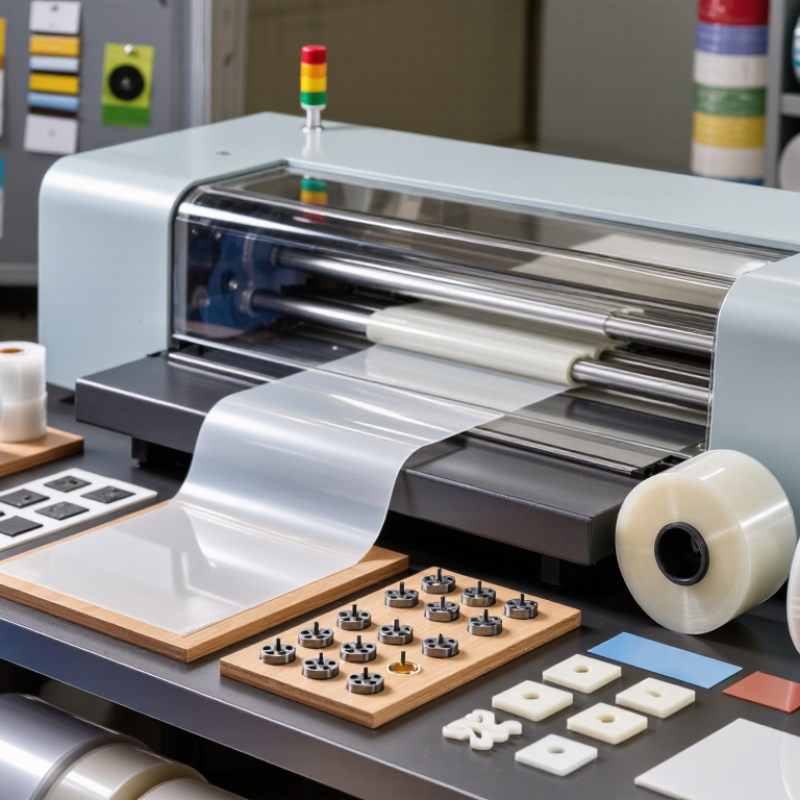
Confirm the machine can process the actual material range, including films, sheets, foams, laminates, and adhesive-backed plastics. |
Different materials require different cutting forces, blade geometries, clearances, and support surfaces. |
Run production samples using the thinnest, thickest, softest, and hardest materials in the planned product range. |
| Working Area |
Maximum sheet or web width and usable cutting length |
Select a working area larger than the largest finished layout, leaving space for registration marks, edge trim, and gripping. |
A correctly sized bed improves nesting efficiency and avoids repeated repositioning of large plastic sheets. |
Compare the usable cutting area, not only the machine’s external dimensions or advertised nominal size. |
| Cutting Force |
Maximum press force and force-control capability |
Choose sufficient capacity for the material thickness, part perimeter, tool design, and number of parts cut per stroke. |
Insufficient force can cause incomplete cuts, while excessive force may damage the tool, cutting board, or plastic surface. |
Request a force calculation or sample-cut report for the intended material and tool configuration. |
| Tooling System |
Compatibility with steel-rule dies, male-female dies, rotary tools, or custom fixtures |
Use a tooling system matched to the part geometry, production volume, tolerances, and required cut features. |
Tool selection affects edge quality, setup time, repeatability, scrap rate, and the ability to add creases or perforations. |
Check maximum tool height, tool mounting method, die-change time, tool storage, and availability of replacement cutting boards. |
| Tool Alignment |
Mechanical registration, locating pins, optical alignment, or camera-assisted positioning |
Use fixed locating features for simple shapes and optical or camera registration for printed, laminated, or multi-layer parts. |
Accurate alignment prevents print-to-cut errors and improves consistency across repeated batches. |
Test alignment accuracy on transparent, reflective, flexible, and printed plastic materials. |
| Cutting Accuracy |
Positioning repeatability and pressure consistency |
Define the required tolerance from the product drawing and confirm repeatability under continuous production conditions. |
Stable positioning and pressure are essential for small holes, narrow webs, close nesting, and multi-layer laminates. |
Measure several consecutive samples rather than accepting a single demonstration piece. |
| Automation Level |
Automatic feeding, indexing, sheet separation, unloading, and stacking |
Choose automation according to batch size, labor availability, material format, and required cycle time. |
Automation can reduce manual handling, improve cycle consistency, and limit damage to delicate plastic parts. |
Verify feeder compatibility with static-prone, flexible, thin, slippery, or stacked materials. |
| Production Speed |
Strokes per minute, cycle time, and effective output |
Evaluate output using the complete cycle, including loading, indexing, cutting, unloading, and tool changes. |
Nominal stroke speed may not represent actual production output when parts require frequent alignment or manual removal. |
Calculate output from a timed trial using the intended tool, material, nesting pattern, and operator process. |
| Waste Reduction |
Nesting software, programmable indexing, and scrap-strip control |
Select controls that support optimized nesting, repeatable pitch, and accurate edge-trim management. |
Efficient material use can reduce plastic waste and lower the cost per finished part. |
Compare material utilization percentages using the same part layout on the proposed machine. |
| Control System |
Recipe storage, touchscreen interface, password levels, and production counters |
Use a controller that stores validated settings for force, stroke, speed, feed length, and registration. |
Stored recipes reduce setup variation and help operators reproduce approved production conditions. |
Confirm backup, restore, user-permission, alarm-history, and data-export functions. |
| Safety Protection |
Guarding, interlocked access doors, two-hand controls, emergency stops, and safety relays |
Choose a machine designed and risk-assessed according to applicable local machinery-safety requirements. |
Die cutting involves high pressure and moving tooling; effective safeguards reduce access to hazardous areas. |
Inspect the safety circuit, guard interlocks, emergency-stop locations, restart prevention, and safe access during tool changes. |
| Operator Ergonomics |
Loading height, tool-change access, visibility, noise, and manual handling requirements |
Prefer clear access, adjustable work height where appropriate, and layouts that minimize lifting and repetitive reaching. |
Good ergonomics can reduce handling errors, fatigue, and the risk of damage to finished plastic parts. |
Observe a complete setup and production cycle with the intended tooling and material weight. |
| Maintenance Access |
Access to lubrication points, guides, sensors, drive components, and cutting surfaces |
Select a design that allows routine inspection and cleaning without dismantling major assemblies. |
Accessible maintenance helps preserve cutting accuracy and reduces unplanned downtime. |
Ask for the maintenance schedule, lubrication chart, wear-part list, and recommended inspection intervals. |
| Cutting Board Management |
Replaceable cutting mat or board, surface flatness, and depth adjustment |
Use a replaceable, suitable-density cutting surface with controlled cutting depth. |
A worn or uneven board can cause incomplete cuts, excessive tool wear, and inconsistent part dimensions. |
Confirm board material, replacement procedure, leveling method, and availability of compatible sizes. |
| Pneumatic and Electrical Requirements |
Power supply, compressed-air pressure, air quality, and electrical protection |
Match utilities to the machine specification and provide clean, dry compressed air when pneumatic functions are used. |
Incorrect air pressure, moisture, or unstable power can cause alarms, inconsistent operation, and premature component wear. |
Verify actual plant voltage, phase, breaker rating, air pressure, flow, filtration, and connection requirements. |
| Quality Monitoring |
Part-presence sensors, cut-depth monitoring, misfeed detection, and alarm logging |
Use sensors and inspection steps that detect missing sheets, double feeds, misalignment, and incomplete cuts. |
Early detection prevents large quantities of defective plastic components from reaching downstream processes. |
Test fault detection with intentional misfeeds, missing parts, incorrect tool positions, and registration errors. |
| Changeover Flexibility |
Tooling interchangeability, recipe recall, quick clamps, and adjustable guides |
Choose fast, repeatable changeover features when the machine will process multiple part types. |
Shorter changeovers increase available production time and reduce setup scrap. |
Time a changeover between two representative products, including tool adjustment and first-piece approval. |
| Service and Spare Parts |
Technical support, documentation, training, and availability of wear parts |
Prioritize documented service procedures and a clear supply route for blades, sensors, seals, belts, and cutting boards. |
Downtime is reduced when common replacement parts and troubleshooting information are readily available. |
Request preventive-maintenance documentation, recommended spare-parts inventory, and response procedures for faults. |
| Total Cost of Ownership |
Machine price, tooling, labor, energy, maintenance, scrap, and downtime |
Compare cost per acceptable part over the expected service life rather than comparing purchase price alone. |
A lower initial price may be offset by higher scrap, slower changeovers, frequent repairs, or expensive tooling. |
Prepare a cost model using planned annual volume, labor rate, material cost, tooling life, and expected utilization. |