


Request a free quote Phone Icon
die cutting materials

Blog

What Is XGS PON SFP and How Does It Work?

Xgs Pon Sfp technology is changing how fiber networks deliver high-speed access. It supports up to 10 Gbps downstream and upstream capacity through a shared passive optical network. Unlike older PON systems, it can serve demanding applications without replacing every fiber cable.

The optical module sits inside an OLT or compatible network device. It converts electrical traffic into optical signals, often using 1270 nm upstream and 1577 nm downstream wavelengths. At the customer side, an ONT receives the signal and sends data back through the same passive fiber path. No powered equipment is required between the central office and the subscriber.

“XGS-PON is fundamentally about combining higher bandwidth with operational simplicity,” says Dr. Glen Hunt, a broadband access technology analyst. His observation is useful, but it should not end the discussion. Real performance depends on split ratio, optical budget, connector quality, temperature, and device compatibility. The label alone proves very little.

A clean installation matters.

A poorly polished connector can create reflections, packet errors, and unstable service. Network engineers must also confirm SFP form factor, transmission distance, wavelength plan, and vendor interoperability before deployment. Some modules appear identical but use different management commands or security settings. This guide explains what an Xgs Pon Sfp contains, how its optical path works, and where practical limitations usually appear. It also examines installation choices that look efficient on paper but may require careful testing in the field.
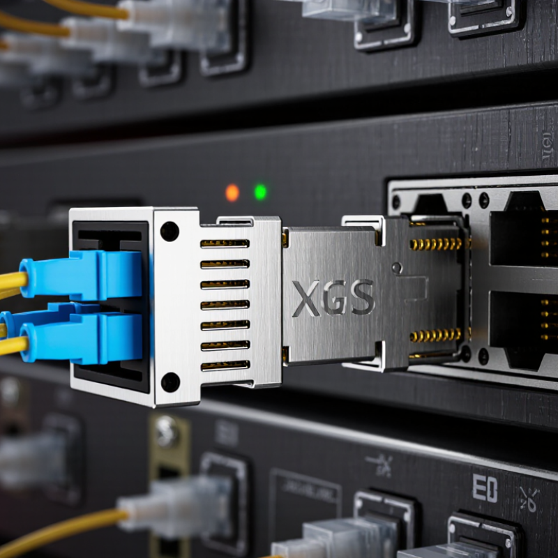
What Is XGS PON SFP and How Does It Work?

XGS-PON SFP: Definition and Core Purpose

An XGS-PON SFP is a pluggable optical transceiver for 10-gigabit passive optical networks. It connects network equipment to a fiber access system. The module converts electrical data into optical signals, then converts received light back into data. XGS-PON supports approximately 10 Gbit/s in both downstream and upstream directions. That symmetric capacity suits business access, mobile backhaul, and high-density broadband services.

The module usually operates with separate upstream and downstream wavelengths, such as 1270 nm and 1577 nm. A passive optical splitter then serves multiple subscribers without powered equipment in the distribution path. This reduces field power requirements and simplifies maintenance. Its core purpose is practical: provide high-speed fiber access through a compact, replaceable interface. Installation still requires matching optical class, transmission distance, split ratio, and connector specifications.

The label can be confusing. Not every SFP-shaped module supports the same PON standard. Engineers should verify host compatibility, optical budget, temperature range, and management functions before deployment. Digital diagnostics can report temperature, voltage, transmit power, and receive power. These readings help identify dirty connectors or excessive loss. Real networks are rarely perfect. Aging fibers, tight bends, and inaccurate power assumptions can reduce stability, even when the module appears correctly installed.

Key Components Inside an XGS-PON SFP Module

An XGS-PON SFP module is a compact optical access device. It connects a host system to a passive fiber network. Inside, the optical engine handles two different directions. Downstream data commonly uses 1577 nm light, while upstream data uses 1270 nm light. A wavelength-division filter keeps these signals separated on one fiber. That small filter does important work.

The transmitter includes a laser, laser driver, and burst-mode control circuit. The driver adjusts current quickly as upstream users transmit in different time slots. On the receiving side, a photodiode converts incoming light into electrical signals. A transimpedance amplifier then strengthens the weak current. Clock recovery and physical-layer logic rebuild clean data for the host equipment. Temperature sensors and digital monitoring report optical power, voltage, and module temperature. These readings help technicians identify a dirty connector or rising optical loss.

An onboard controller stores identification data and manages alarms. It also communicates through the SFP management interface. The module must maintain strict timing, because many subscribers share one passive optical path. Real installations are less tidy. Fiber reflections, heat, and aging connectors can reduce margin. That detail matters. A module may pass a bench test yet perform poorly in a crowded cabinet. Engineers should check optical budgets, receiver sensitivity, and thermal conditions together. The design seems small, but its responsibilities are not. One limitation deserves attention: monitoring values are useful indicators, not absolute proof of fiber health. Physical inspection still matters.

How XGS-PON SFP Transmits Data Through Fiber

An XGS-PON SFP is a compact optical transceiver for ten-gigabit passive optical networks. It connects network equipment to a single-mode fiber link. Unlike ordinary Ethernet optics, it communicates through a shared passive optical distribution network.

The optical line terminal sends downstream data continuously, commonly near 1577 nm. A splitter then distributes the signal to many optical network units. Each unit checks the frame and accepts only its assigned data. The SFP converts electrical signals into laser pulses, and its photodiode converts incoming light back into electrical data. Fiber carries the information as rapid changes in light intensity.

Upstream transmission works differently. Several users share the same fiber, so they cannot transmit freely at the same time. The network assigns short time slots, creating controlled burst transmissions around 1270 nm. The SFP adjusts its laser quickly, while the receiving equipment separates each burst by timing and network identifiers. Forward error correction helps recover damaged data, although it cannot fix every physical problem.

In practical installations, connector cleanliness matters more than many teams expect. A small particle can increase loss or cause unstable readings. Optical power, wavelength, and link distance should be checked against the equipment specifications. Standards can also allow different wavelength details. That assumption needs verification. The design looks simple, but split ratios, fiber bends, and burst timing can change real performance.

Network Roles and Compatibility of XGS-PON SFP

An XGS-PON SFP is a compact optical module for 10-gigabit passive optical networks. Its network role depends on where it is installed. In an OLT, it connects the service platform to the fiber distribution network. In an ONU or ONT, it provides the customer-side optical connection. The module carries downstream and upstream traffic over shared passive fiber. It also handles optical conversion, timing, and PON transmission rules.

Compatibility involves more than speed. The host device must support the module’s electrical interface, management functions, and software control. The optical class must match the network budget, including fiber length, split ratio, and connector loss. Wavelength support is critical as well. XGS-PON commonly uses separate downstream and upstream wavelengths, so an ordinary Ethernet SFP cannot replace it. The enclosure may fit, but the protocol will not.

A practical check should include the host port, firmware, optical class, and temperature range. Some modules report useful details, such as transmit power and receiver status. Others provide limited monitoring. That difference can complicate troubleshooting. Coexistence with another PON technology may also require specific wavelength plans and network equipment support. The label alone is not enough. Field installers should confirm interoperability before deployment, especially in mixed networks. A small mismatch can cause unstable registration, weak optical margins, or no service at all. Compatibility tables are helpful, but real testing remains important.

What Is XGS-PON SFP and How Does It Work?

Nominal downstream and upstream line rates of common passive optical network standards

XGS-PON is a symmetric passive optical network technology defined by ITU-T G.9807.1. It provides approximately 10 Gb/s in both the downstream and upstream directions, using a shared optical distribution network between the OLT and multiple ONUs.

An XGS-PON SFP is a pluggable optical module used to connect compatible network equipment to the fiber access network. The module typically handles optical transmission, reception, wavelength conversion, and PON protocol functions. It must match the host device, optical budget, operating wavelengths, and XGS-PON OLT/ONU ecosystem; an ordinary Ethernet SFP cannot provide XGS-PON operation by itself.

Deployment Factors for Choosing an XGS-PON SFP

An XGS-PON SFP is a pluggable optical module for passive fiber access networks. It connects network equipment to an XGS-PON optical line. The technology supports approximately 10 Gbps downstream and upstream transmission. Unlike ordinary Ethernet optics, it works with passive splitters and shared optical paths. A small module can serve homes, offices, or mobile sites through existing fiber infrastructure. However, compatibility depends on more than speed.

Deployment factors for choosing an XGS-PON SFP include optical budget, reach, splitter ratio, and operating temperature. A long fiber route with several splitters needs stronger receiver sensitivity and suitable transmit power. Check the required wavelengths carefully, because upstream and downstream signals use different optical bands. The host device must also support the module’s electrical interface, software controls, and management functions. Field experience shows that heat is often underestimated. A crowded cabinet can reduce stability. A perfect design rarely survives real installation conditions, so leave practical margin for aging, dirty connectors, and future changes.

Tips: Confirm the module against the OLT or access platform before ordering. Measure actual fiber loss instead of relying only on drawings. Clean every connector and record power readings during commissioning. Keep spare units in controlled storage. It sounds excessive, but troubleshooting a remote optical fault is rarely quick.

What Is XGS-PON SFP and How Does It Work? - Deployment Factors for Choosing an XGS-PON SFP

Deployment Factor Typical XGS-PON SFP Specification Why It Matters Selection Guidance
PON Standard XGS-PON, ITU-T G.9807.1 Defines the optical signaling, transmission rates, wavelengths, and interoperability requirements. Choose an SFP explicitly designed for XGS-PON rather than a conventional Ethernet optical transceiver.
Downstream Rate Nominally 9.95328 Gb/s Provides a shared downstream capacity of approximately 10 Gb/s for connected subscribers. Confirm that the host equipment and service design can process the full line rate.
Upstream Rate Nominally 9.95328 Gb/s Enables symmetrical upstream and downstream PON capacity, subject to shared-medium utilization. Evaluate peak concurrent demand, traffic profiles, and the optical line terminal's scheduling capability.
Downstream Wavelength Approximately 1575–1580 nm Carries downstream data and supports coexistence with selected legacy PON services on the same fiber. Verify the exact wavelength range against the optical plan and coexistence filters.
Upstream Wavelength Approximately 1260–1280 nm Uses a separate optical band for upstream transmission and wavelength-division multiplexing. Check compatibility with splitters, filters, patch panels, and existing PON technologies.
Optical Budget Common classes include N1, N2, E1, and E2; exact loss limits vary by class Determines the maximum allowable loss between the PON port and the optical network unit. Calculate fiber attenuation, splitter loss, connector loss, splice loss, and engineering margin before selecting the class.
Reach Typically up to 20 km logical reach; practical distance depends on the optical budget Limits the physical distance between the central office or access node and subscriber premises. Use the actual route length and loss measurement instead of relying only on the nominal reach value.
Split Ratio Common deployments include 1:32 and 1:64; higher ratios are network-dependent A higher split ratio increases subscriber density but also adds optical loss and reduces shared capacity per user. Balance subscriber count, bandwidth demand, optical loss, and future expansion requirements.
Host Interface SFP+ form factor; host-side electrical interface generally supports 10 Gb/s operation Ensures the optical module can physically and electrically operate in the target access platform. Check cage compatibility, supported module coding, power limits, firmware requirements, and management functions.
Operating Temperature Commercial, extended, or industrial temperature ranges may be available Temperature affects optical power, receiver sensitivity, reliability, and service continuity. Select a range suitable for the installation location, such as a controlled room, cabinet, or outdoor enclosure.
Connector Type Usually a single-fiber connector interface such as SC/APC in PON access equipment The connector polish and type influence return loss, insertion loss, and physical compatibility. Match the module connector with the patching system and avoid mixing angled and non-angled polish types.
Fiber Type Single-mode fiber, commonly compliant with ITU-T G.652 or compatible access-fiber designs Single-mode fiber supports the long distances and wavelength ranges used by XGS-PON. Confirm fiber specifications, bend performance, attenuation, and installed plant condition.
Monitoring and Management Digital diagnostics may report temperature, voltage, bias current, transmit power, and receive power Diagnostics simplify fault isolation and help identify fiber degradation or optical-level problems. Prefer modules whose monitoring data is recognized by the target platform and network management system.
Coexistence Requirements May coexist with GPON or other PON generations through wavelength separation Allows migration to higher capacity while preserving portions of the existing outside plant. Validate optical spectrum allocation, coexistence elements, insertion loss, and central-office equipment support.
Budget and Capacity Planning Shared 10 Gb/s-class capacity with service-dependent oversubscription Actual user performance depends on the number of active subscribers and traffic scheduling. Model busy-hour demand, subscriber growth, service tiers, and upgrade headroom before final deployment.

Article Source: